Dartmouth magnetics logo Dartmouth Magnetic Component and Power Electronics Research
Transformers and Inductors for Electronics Applications

Home

Research Topics

Publications

People

Free Software

Information for Designers

Links

Sponsors

Guide to Litzopt Online

Page 1  Page 2Page 3

Throughout the online interface, many words are highlighted and link to a popup window with an explanation and brief instructions relevant to the context. The instructions here are similar and more detailed.


Simulation Mode Layered Windings Number of Windings Current Waveform Specification Mode
Simulation Mode

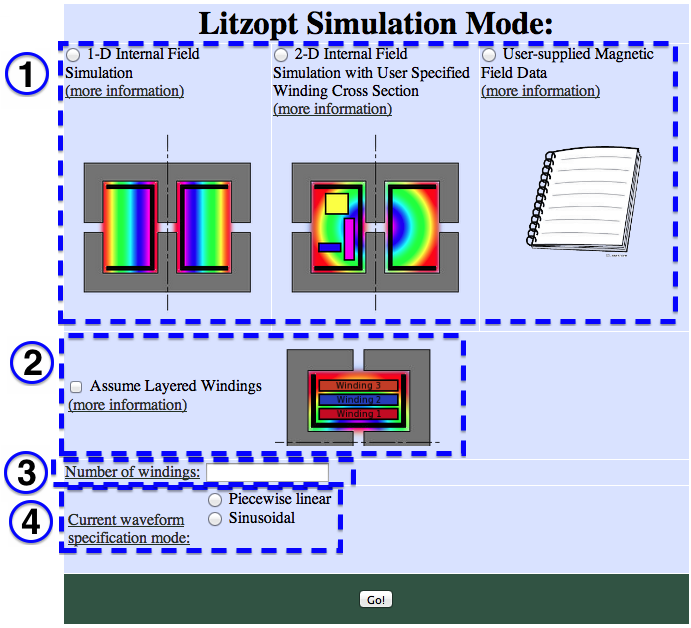
1-D Internal Field Simulation:

The 1-D simulation is less accurate than the 2-D simulation but doesn't require the user to specify the specific winding geometry. The difference can be particularly significant in cases with high magnetizing currents that occur with relatively low-permeability or widely gapped cores.

It assumes a radially- and axially- symmetric magnetic field. One aspect of this symmetry is magnetic field lines that are all parallel to the center axis of the inductor windings.

Inputs:

  • current waveform
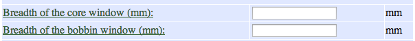
  • core window height and breadth
  • gap location
  • winding packing factor
  • wire size and build
  • turn length and number of turns.

2-D Internal Field Simulation with User Specified Winding Cross Section:


The 2-D simulation is more accurate than the 1-D simulation but requires the user to specify the bobbin window dimensions (in addition to the core window). The 2-D simulation can be particularly advantageous versus 1-D in cases with high magnetizing currents that occur with relatively low-permeability or widely gapped cores.

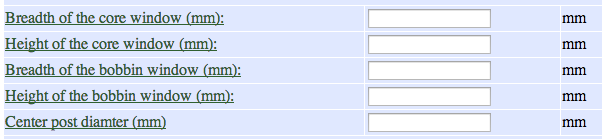
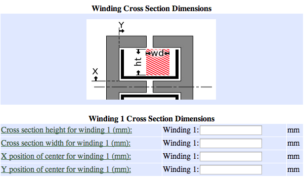
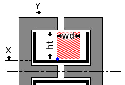
The "user specified winding cross section" mode allows the user to specify the specific geometry of the winding cross section (unless "assume layered windings" is checked), rather than assuming that the windings are simply stacked as in the "2-D, layered" option. dimensions of each winding cross section. It runs a finite element model that takes into account axial and radial components of the magnetic field, and assumes that the field is rotationally symmetric about the center of the winding.

Inputs:

  • piecewise linear current waveform for each winding
  • core and bobbin window dimensions
  • core gap length and location
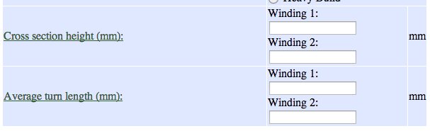
  • winding turns and turn length
  • wire gauge, build and packing factor
  • cross-section dimensions of the winding (i.e. where the winding is located within the winding window, and its height and breadth).

User-supplied magnetic field data:

This option allows the user to input their own values for the magnetic field analysis, i.e. from an external finite element simulation software. In addition to the piecewise linear current waveform, core and bobbin window dimensions, winding and wire specifications, the user must input the volume of each winding, and the integral of the square of the magnetic field (in T^2) over each winding with 1 amp simulated in it and each of the other windings, as well as 1 amp in different combinations of all of the windings (details will be specified in the following prompts).

Additional instructions are provided on the "Using your own FEM software" page.


Assume layered windings

"Layered windings" assumes that the windings fill the bobbin window and stack radially (as pictured). The windings take up the full breadth of the bobbin.

The heights of the windings are set such that they are proportional to the current integrated over the cycle and the number of turns of wire. The equation is: Hti = [Ni*Irms,i / Σ(N Irms)] * Ht_window. The turn lengths are calculated by determining the radial coordinate of each winding, and multiplying by 2π.

By selecting this option, the user does not need to specify turn lengths or any winding cross section information. However, the center post diameter, core and winding window heights (only otherwise needed for 2-D mode), will be specified on the next page.

1-D Mode with layered windings assumption and all cases in 2-D mode.

Without layered windings selected, 1-D mode does not take bobbin and core height as an input:

1-D mode without layered windings assumption
1-D Mode without layered windings option.

Without the layered windings option, the user must specify the winding geometry. For 1-D mode, the next page will contain:

1-D without layered windings assumption
1-D Mode without layered windings option.

In 2-D mode without layered windings, the user will be able to specify the details of each winding cross section on the next page:

2-D without layered windings assumption
2-D Mode without layered windings option.

The "User-supplied Magnetic Field Data" mode will take similar inputs to the 1-D simulation mode with and without the layered windings assumption, in addition to the magnetic field data.


Number of windings

The number of separate windings on the core. For example: 1 for a simple inductor, 2 for a simple transformer with a primary winding and a secondary winding. For each winding, the user can specify the current waveform, number of turns, wire gauge and construction, and geometry (if applicable).

Current waveform specification mode

The current waveform used to excite each winding for optimization can be entered as a piecewise linear or sinusoidal specification. In sinusoidal mode the inputs taken on the following page are frequency, amplitude in amps, and relative phase angle of the sine wave between windings.

The piecewise linear option requires the number of time steps in the waveform. A corresponding prompt will appear when the piecewise linear option is selected. On the following page, the user will specify the current in amps at the beginning of each time step and the duration of each time step. At least two time steps are required. A symmetric triangle wave, for example, would be defined with two time steps of equal duration.