Transformers and Inductors for Electronics Applications
|
Transformers and Inductors for Electronics Applications |
|
|
Instructions for Computing the Flux Density:Litzopt uses magnetic field data to assess winding losses. The data used is the square of the magnetic flux density (B) integrated over the volume of each of the windings in the transformer. These values are to be computed for all combinations of one- and two-winding excitations in the transformer. The excitation sequence is generated by Litzopt for any given number of windings. (see a Litzopt data file for an example of the sequence of winding excitations). Obtaining the Integral of Squared Flux DensityUsers with access to numerical electromagnetic analysis software (e.g. Maxwell) can obtain the necessary field values by constructing the transformer winding window and running a simplified "magnetostatic" simulation. The required magnetostatic field simulation requires far less computation time than a conventional field simulation and all that is to be computed is the spatial integral of squared flux density over the regions of uniform winding density. The simulation can be performed in two or three dimensions. Three-dimensional simulations can accommodate any core geometry but are less computationally efficient. Two-dimensional simulations offer greater computational efficiency and can be used to obtain an approximation of the magnetic flux density (B) of a three-dimensional device. More information regarding the use of two-dimensional simulations to model a three-dimensional geometry is available here. For a given winding excitation, all of which consist of unit current (NI = 1 ampere-turn) in one winding or unit currents in two windings considered simultaneously, the volume integral of the squared field value considered over a winding is defined as the spatial integral of the squared field everywhere within the volume occupied by the winding. For a given excitation, this calculation is to be repeated over the volume of each of the windings in the device. When the volume integral of squared field has been obtained in each transformer winding, the user is to apply current through the winding(s) excited in the next winding excitation sequence in the data file. Three-Dimensional SimulationsUsers simulating in three dimensions are to draw the transformer and obtain the integral of squared flux density over each of the regions specified in the winding excitation sequence. The user is to draw the transformer and follow the sequence of excitations with a total NI of 1 ampere-turn in the excited windings (corresponding to a winding current of I = 1 ampere/N).  A three-dimensional drawing of an ecore-transformer Two-Dimensional SimulationsTwo-dimensional simulations are often used to obtain approximations of magnetic fields in three-dimensional devices. Most core geometries can be accommodated using two-dimensional solutions. Unfortunately, the following two-dimensional simulation procedures cannot accommodate all core geometries (e.g. toroidal). Users simulating in two dimensions are to draw the transformer by 'slicing' through the center and drawing the resulting cross section (see example below). The windings' cross sections are to be considered as regions of uniform current and so each winding cross section is to be drawn as a rectangle. The user is to obtain the volume integral of squared magnetic flux by multiplying the area integral of squared flux density over the winding cross-section from the two-dimensional simulation by the average length of a winding turn (2πr); to be computed for each winding (see example). An alternate method of obtaining the volume integral of squared magnetic flux is by performing a RZ (cylindrical) simulation by integrating over an incremental volume of 2πr dA with the integrand being the quantity B2 dA. The resulting integral values are to be multiplied by the factor 2π to obtain the volume integral over each of the winding regions. 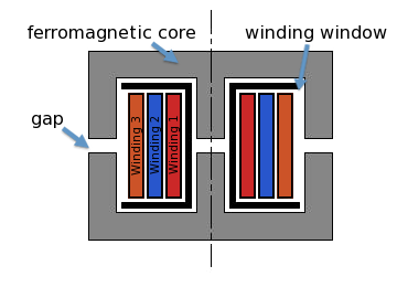 A cross-section of a typical winding window. The windings are in blue, red and
orange and are considered as regions of uniform current density.
|