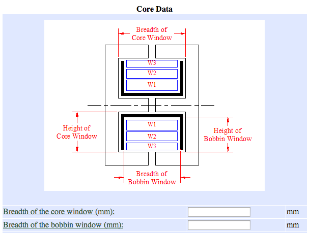
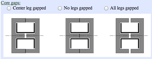
If "Assume Layered Windings" is not selected in either 1-D or user-supplied simulation mode, only the core and bobbin window width need to be specified. In other modes, the core and bobbin window height and the core gap are required. The core gaps specification is required in all simulation modes:
User must select whether the center, outer, or all legs of the core have a gap.
Current waveform
The current waveform may be specified as a sinusoid with frequency, amplitude, and phase, or as a piecewise linear function. This is selected on the first page of inputs.
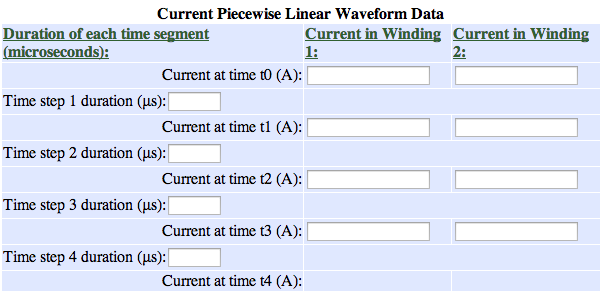
Piecewise linear waveform parameters
The piecewise linear mode of specification takes duration and starting current flow for each time point and each winding. The number of windings and the number of time points are specified on the previous page. The form automatically fills in the current value for the end of the last time step, which physically must be identical to that of the start of the first time step. All windings run at the same frequency, and are defined by the same time segments.
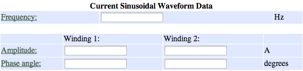
Sinusoid waveform parameters
The sinusoidal mode of current waveform specification takes frequency for all windings, plus amplitude and phase for each individual winding.
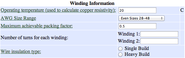
Winding specification
All simulation modes require several details about the construction of the windings.
General winding parameters (2-D simulation pictured)
If "Assume Layered Windings" is selected, litzopt will estimate the remaining parameters as described on the previous page. In other modes, more inputs are needed to define the simulation. The average turn length for each winding will not be calculated without the layered winding assumption, and must be entered manually. In the 1-D simulation mode, the cross section height (or radial dimension) of each winding is entered manually. In the 2-D mode, the position, height and width of the cross section of each winding can be entered.
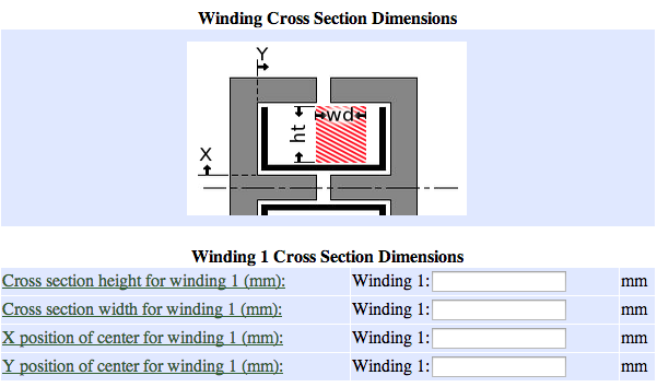
2-D winding specification
Only rectangular cross sections can be defined. If the defined cross sections extend outside the bobbin window or overlap one-another, an error message is provided. The winding shapes can be previewed by selecting "Preview Winding Cross Section".
Optional preview of winding cross section. This link will provide a popup with the cross section illustrated.
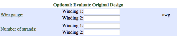
Evaluate original design
This optional section will compare a user-specified winding to the optimized designs in both relative cost and predicted efficiency.
Optional user-specified design for comparison to optimal