Transformers and Inductors for Electronics Applications
|
Transformers and Inductors for Electronics Applications |
Variable Definitions:Amplitude - The peak current of a sinusoidal waveform, i.e. half of the peak-to-peak current. Breadth of Bobbin Window - Required for all simulation modes. The breadth of the bobbin (in millimeters); the dimension parallel to the center leg as shown in Figure 1. Breadth of Core Window - Required for all simulation modes. This dimension is taken in the direction parallel to the center leg, as shown in Figure 1. 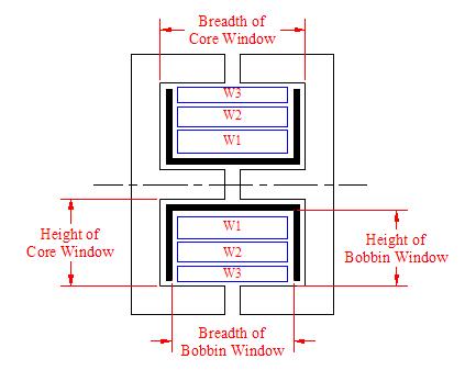 Figure 1: Bobbin and Core Window Dimensions Center post diameter - The diameter in millimeters of the center post in the magnetic core. For a square centerpost, use diameter = perimeter/pi. The centerpost diameter and the radial location of the center are used to calculate the average turn length of each winding. Force Fixed Number of Strands - This mode takes the specified number of strands and draws a rectangular winding the full breadth of the winding window, with radial dimension necessary to accommodate the number of strands, and bordering the inner boundary of the window. In this mode, ShapeOpt will not perform any optimization, but will calculate loss, magnetic field integrals and winding parameter information, which can be used for design purposes or as comparison to the shape-optimized design. Force Full Bobbin - This mode assumes that the winding cross section fills the winding window of the bobbin, and will not perform any optimization. In this mode, ShapeOpt will calculate loss, magnetic field integrals and winding parameter information, which can be used for design purposes or as comparison to the shape-optimized design. Frequency - The operating frequency of the inductor in hertz. Gap Length - The length in millimeters of the air gap in the magnetic core. If "No legs gapped" is selected for the gapping configuration, this value will be ignored, and the gap length will be set to zero. Gap Location - The location of any air gaps in magnetic core. Select gapping configuration from the images shown. If "No legs gapped" is selected, the gap length parameter, if specified, will be ignored (and the gap length will be set to zero). Height of Bobbin Window - The available winding height, calculated as the distance from the inner radius of the bobbin to the inner edge of the core, as shown in Figure 1. This dimension is required for the two dimensional analysis or for all modes with the layered windings assumption. Height of Core Window - It is taken in the direction perpendicular to the center leg, as shown in Figure 1. This dimension is required for the two dimensional analysis or for all modes with the layered windings assumption. Horizontal divisions in each winding - Number of horizontal divisions of each winding for finite element calculation (20 divisions is the default). Number of images of the Winding Window Geometry to be computed in the x-direction - Number of images of the Winding Window Geometry to be computed in the x (vertical in figures above) direction for finite element simulation. Five images is the default, typically sufficient for 0.05% accuracy (J. Pollock, T. Abdallah, C. R. Sullivan, "Easy-To-Use CAD Tools for Litz-Wire Winding Optimization" Feb. 2003). For a detailed explanation of the method of images, see P.J. Lawrenson K.J. Binns and C.W. Trowbridge, The Analytical and Numerical Solution of Electric and Magnetic Fields, J. Wiley, 1992. Number of images of the Winding Window Geometry to be computed in the y-direction - Number of images of the Winding Window Geometry to be computed in the y (horizontal in figures above) direction for finite element simulation. Five images is the default, typically sufficient for 0.05% accuracy (J. Pollock, T. Abdallah, C. R. Sullivan, "Easy-To-Use CAD Tools for Litz-Wire Winding Optimization" Feb. 2003). For a detailed explanation of the method of images, see P.J. Lawrenson K.J. Binns and C.W. Trowbridge, The Analytical and Numerical Solution of Electric and Magnetic Fields, J. Wiley, 1992. Number of Turns - The number of turns of wire in each winding. Override wire diameter - Check the box to directly input wire outer diameter in millimeters. The wire build and wire gauge inputs will be disabled. Wire Packing Factor - Packing factor describes the ratio of the cross sectional area occupied by the wire cross section versus open space for the winding expressed relative to "perfect square packing". Thus the packing factor takes into account both the packing of individual litz wire bundles and the packing of whole bundles on each other into a winding cross section. Perfect square packing occupies π/4 of the area. So, for example, a winding with packing factor of 0.5 would have wire cross section occupying π/8 of the window cross sectional area. A typical number for litz wire is Fp = 0.35, resulting in 28% of winding area occupied by copper. Temperature - Required to determine the resistivity of copper for calculation. The temperature entered should be the operating temperature of the magnetic component in degrees centigrade. The electrical resistivity of copper is 1.7241 x 10 -8 Ωm at 20 C. We use the following linear approximation to adjust for the temperature:ρ(T) = ρ0[1+α(T-T0)] where the temperature coefficient α = 0.0039 K-1 and ρ0 is the input temperature. Vertical divisions in each winding - Number of vertical divisions of each winding for finite element calculation (20 divisions is the default). Wire Insulation Type - The insulation build on the wire used for the windings in magnetic component. The thickness of the insulation layer on the wire affects the outer diameter used in calculations and determines what designs will fit in the bobbin window. The formula used is dt = dr*alpha * (dc/dr)^beta where dt is the outer diameter including insulation, dr is the diameter (m) of AWG 40, and dc is the diameter (m) of of the wire used. The constants alpha and beta are 1.12 and 0.97 for single build and 1.24 and 0.94 for heavy build respectively. The formula y = 0.0050*(92)^((36-x)/39) is used to convert AWG (x) to inches diameter (y). Wire gauge - AWG (American Wire Gauge) size for the winding. The formula y = 0.0050 * 92^((36-x)/39) is used to convert AWG x, to inches diameter, y. |