|
Home
Research Topics
Publications
People
Free Software
Information for Designers
Links
Sponsors
|
Example Inputs
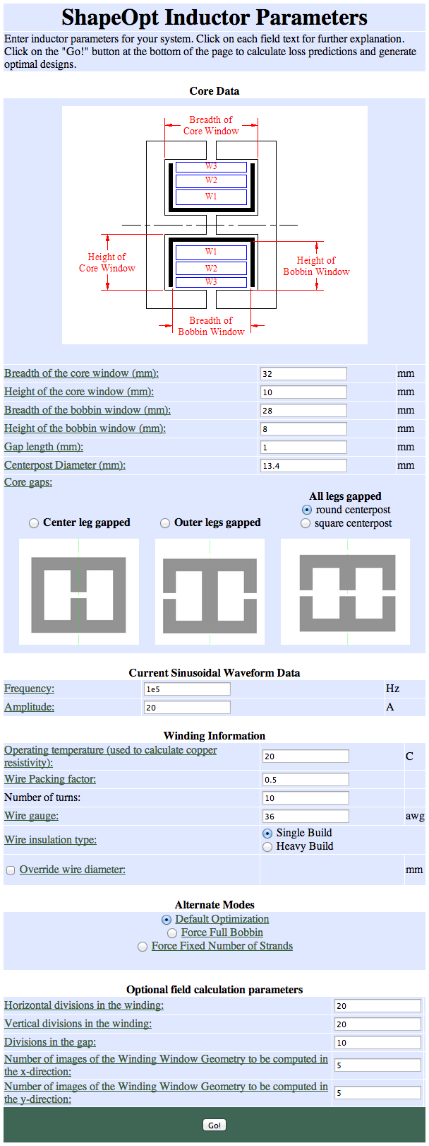
Figure 1: Example inputs (EC52 core and bobbin).
Example Results
|
ShapeOpt Results: Optimized Winding Design |
|
If your current waveforms or window and winding cross-sections
are not correct, use your internet browser's 'Back' button
to edit your data. |
|
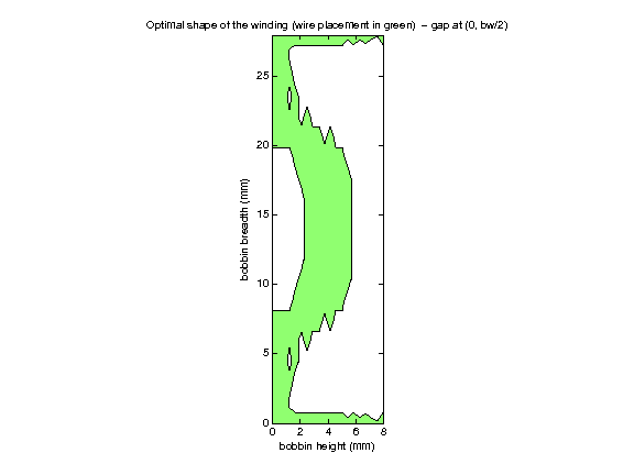
Optimal Winding Shape |
|
|
Optimal Winding Information |
| Number of strands |
226 |
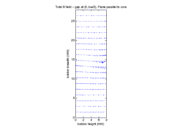
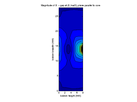
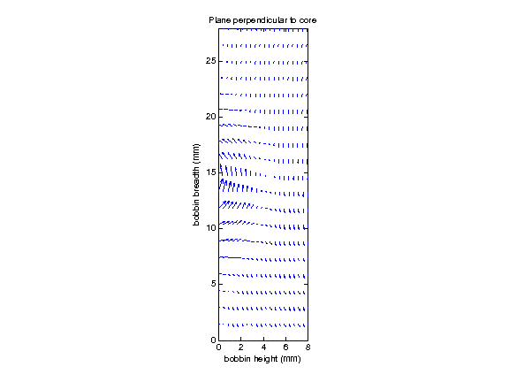
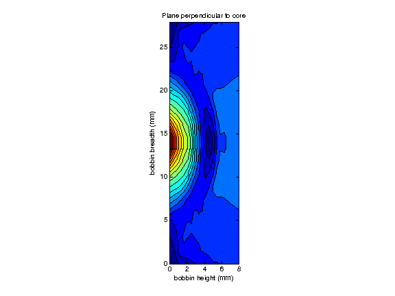
| ∫∫ B2⋅dS over winding area |
4.84089e-09 T2⋅m2 |
| Average turn length |
0.129317 m |
|
Power Loss |
| AC loss |
1.14717 W |
| DC loss |
1.47424 W |
| Total loss |
2.62142 W |
|